With summer approaching, many have already opened the cycling season, and some are just preparing for it. In any case, if you frequently use two-wheeled vehicles, it is worth considering a speedometer to measure your current speed and distance traveled. It's boring to just go and buy an accessory in the store, so we suggest paying attention to creating your own speedometer on the Arduino platform. Everything will take no more than a couple of hours, and the project budget is less than 500 rubles. As a result, you should get an accessory in which a servo drive with an arrow and a scale will show the current speed in analog form, and the display will show the distance traveled.

Installation tools and accessories
Shoe sponge box
Drill, scissors, soldering iron
Thick cardboard, Marker
Toothpick, paint
Heat-shrink tubing
Glue gun and superglue


Optionally, you can put a second speedometer to check the accuracy of the readings of the homemade gadget. However, this is not necessary, since this is a fairly simple device and it is unlikely that something could go wrong with you during the assembly process. What is important, unlike similar store accessories, a homemade speedometer is more resistant to damage and can be used even by those who like aggressive driving on rough terrain.
“If one person screwed something to something, then another can always unscrew it” - a popular saying, most widespread among locksmiths - repairmen, and was remembered due to the fact that it was necessary to install a recently purchased bicycle on a bicycle. He was not afraid of theft (now such prospects are open to gentlemen crooks ...), but yes, mischief. What kid doesn't like taking risks? Not for the sake of profit, but to test your ability to "act". Therefore, the classical fastening, with the use of screeds, did not suit. To complicate things, by passing the wire inside the front fork it was lazy, and anyway they would tear something off. I decided to make a completely removable version.
In the standard installation, plastic ties are used, it is fast, elegant, but completely unreliable if a bike equipped with a speedometer has to be left somewhere, even with a cable lock, but still unattended.

The option to easily remove the entire device, take it with you, and then put it back in place became possible thanks to a removable screw clamp from the fishing reel. In the photo to the left of the platform for installing the electronic unit, what was immediately removed from the kit. And on the right is a new flat and thicker platform support, cut from plastic, on which holes are drilled both for fastening with a platform and with a screw clamp.

In the attachment site, for a more reliable connection with the support, four "blind" holes were drilled through, and the existing self-tapping screws were replaced with longer ones.

Mounting plate, support and screw clamp assembly. Basically, self-production such a clamp does not present any difficulty at all. Two grips with a bend inward, a screw passes through the hole in the bend, at its end there is a washer with a nut. A plastic grip is installed on the screw head for screwing.

Speedometer assembled and mounted on the handlebars of the bike. In the process of use, the ability to easily change the installation location will allow you to choose the most convenient for observation.

The awkwardly protruding sensor wires are laid in a groove running along it, on the one hand, it turned out to be tightly inserted into the existing plastic grip, and on the other, they were fixed with a short piece of tie through the existing holes. Now you can be sure that the wire will not fall off on the first trip.

In a square aluminum pipe with a length corresponding to the length of the sensor, a slot is made for its working part, which, after installation, protrudes a few millimeters beyond the dimensions of the pipe. This will make it possible for the reed switch inside to clearly record the passage of the magnet mounted on the spoke past it.

An impromptu bracket made of a strip of metal is attached to the pipe, by means of which it is installed on the threaded part of the front hub axle. The result is a sensor holder.

The sensor holder is in working position, there is a sensor in it, a magnet in a plastic cage is attached to the spoke. In addition, we managed to comply with the recommendation for installing the magnet as close to the bushing as possible, which will reduce the speed of its passage past the reed switch and, accordingly, increase the time required for its operation. Taking into account the vertical arrangement of the holder, it is possible to completely exclude the possibility of the sensor falling out of it; moreover, it becomes in place with a slight interference.

When attaching a clip with a magnet to a wheel spoke, it may be difficult to tightly connect its two halves. It is eliminated by biting off part of the self-tapping screw or replacing it with a shorter one.

The bike computer is installed on your workplace and ready to go. The use of such an attachment option, firstly, makes it possible to take it on a trip only when it is needed, to wash and repair the bike without interference, and of course a 100% guarantee of that. that he will always be yours ;-)
The installation time, if desired and with some skill, can be literally brought to seconds. Withdrawal takes an identical amount of time. Especially for, the author of the article Babay iz Barnaula.
After buying a new bike, I decided to equip it with a cycling computer, but I didn't buy Chinese crafts for three reasons:
1. High price
2. Disgusting build quality
3. Well, I'm a radio amateur!
And so I acted like a real radio amateur - I assembled the desired device myself.
In this article I will tell you how to assemble a bicycle computer on a microcontroller yourself. This cycling computer is made on the Attiny2313 microcontroller, a one-line LCD indicator on the HD44780 controller is used as a display. The device can display the current speed, total and intermediate distances (displayed in meters). The total distance, in contrast to the intermediate distance, is stored in the non-volatile EEPROM memory. The bike computer circuit is very simple and does not contain expensive components:
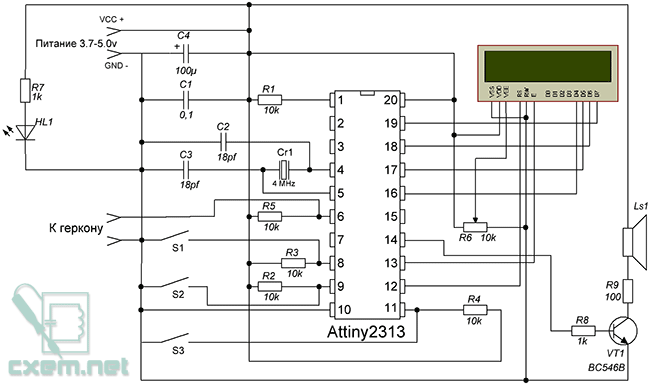
The display is connected to the microcontroller via a common 4-bit interface. The buttons S1, S2, S3 (pulled up by ten kilohm resistors to the power supply plus) control the device. The trimmer R6 adjusts the contrast of the display. HL1 LED indicates power supply. A piezo emitter can be used as the Ls1 speaker. Transistor VT1 - you can put any bipolar n-p-n structures, for example KT315 (I used BC546B). The Attiny2313 microcontroller can be used with any letter indices.
Why do you need an external crystal for a microcontroller that has its own clock generator?
Probably, each of you has such a question, and I will try to answer it. Without quartz, the operation of the device will be extremely unstable (measurement inaccuracy, cracks on the display, etc.) because the built-in clock generator in the microcontroller has a large "floating point" and its frequency constantly fluctuates. If you do not have such a quartz, do not be discouraged! Just change the program to match the quartz you have. Write on the line $
crystal = frequency of your quartz and everything will be OK. But at worst, if you do not have any crystal, use the built-in clock generator (example of setting the fuse bits below), of course it will not work quite accurately and stably.
After I drew a diagram and thought about what the bike computer would be, I got on my favorite bike and drove around the city to buy radio parts according to the following list:
- Microcontroller Attiny2313 1pc.
- Tact buttons (without latching) 3pcs.
- Resistors with a nominal value of 10 kOhm 5 pcs.
- 1 kOhm resistors 2 pcs.
- Resistor 100 Ohm 1pc.
- Socket for DIP-20 microcontroller 1pc.
- Bipolar transistor BC546B 1pc.
- Piezo emitter 1pc.
- Quartz 4 MHz 1pc.
- LED (blue light) 1 pc.
- Building resistor with a nominal value of 10 kOhm 1 pc.
- LCD indicator (display) on the HD44780 controller 1 * 16 1pc.
- Ceramic capacitors 18 pF 2pcs.
- Ceramic capacitor 0.1 uF 1pc.
- Electrolytic capacitor 100 uF 1 pc.
- Plug 2.5 1pc.
- Socket for plug 2.5 1pc.
- MiniUSB socket 1pc.
- Plastic case 85x60x35mm 1pc.
- Bicycle handlebar mount 1pc.
- Latching button 1pc.
- Reed switch 1pc.
The case I bought for the bike computer:

I had a breadboard, heat shrink, battery and wire meter.
Arriving home, I immediately took up the assembly of the bike computer. First of all, I took up the case. Make a 15x60mm rectangular hole in the case.
Perhaps you ask, how did you make such a hole? It's very simple! First, we mark with a pencil where we will make a hole, then with a drill we drill along the contour of the hole when the entire contour has been drilled out, break out a piece of plastic and process everything with a file. Here's what I got:

By the way, I made all the other holes during the assembly. From the inside of the case, I glued a piece of organic glass to the hole to prevent dust and moisture from getting on the display.
Back view (without cover):


My device is powered by a 3.7v Nokia phone battery. Charging is carried out via the MiniUSB port connected directly to the battery. Perhaps you will say that this is not correct! And you will be right, there are special microcircuits for this business, but I did not find such a mikruhi and had to be content with what it was. But after all, charging is in progress, and in two hours of charging, my battery is fully charged. In the operating mode with the display backlight on, the cycling computer consumes ~ 30mA.
Installing the bike computer on the bike
To count the distance and speed, the bicycle speedometer needs, so to speak, a "sensory organ". The reed switch is this “organ”, it is installed on the bicycle frame next to the wheel, a magnet is installed on the spokes of the wheel. So that when the wheel makes a full revolution, the magnet “passes” opposite the reed switch and “closes” it, thereby forming the impulse that the bike computer needs to calculate the distance and speed. The diagram shows where to connect the reed switch to the device. I soldered a reed switch to a small piece of a breadboard, soldered wires to it and shrink it on it. And he fixed it all on the bike frame with plastic ties.

An example of installing a magnet on the spokes of a wheel:

I fixed the bike computer in the middle of the handlebars:
Description of the device
When the device is turned on, a greeting and information about the version and author appears on the display, then the intermediate distance is shown on the left side of the display, and the speed on the right (main screen).
S1 button- when pressed, the total distance is saved in the non-volatile memory EEPROM, for a second the display shows the inscription "All:" and after its total distance and the inscription "Save", sounds sound signal and then the cycling computer returns to calculating distance and speed (main screen).
Yes Yes! You are not mistaken (looking at the photo above), in a few days I drove 191 km! Because today (21.08.2012), there are 11 left to go to school, and in order to spend the summer I decided to make a “small” ride out of town.
S2 button- when pressed, the intermediate distance is reset, the display shows the message “Total clear!”, a beep sounds, after which the bike computer returns to calculating the distance and speed (main screen).
S3 button- when pressed for a second, the display shows “All:” and then its total distance and a sound signal sounds, after which the bike computer returns to calculating the distance and speed (main screen).
Setting up the bike computer
In order for the bike computer to display the correct distance and speed, it must know how far the bike travels in one wheel revolution (otherwise the device will simply incorrectly read the distance and speed), this distance is stored in a constant Coleso(I have a default of 2.08 meters). To set up the bike computer, measure the wheel length of your bike in centimeters, convert the resulting value into meters and enter it into a constant Coleso, recompile the program with the new values and flash it on the bike computer.

If anyone is unable to do this, send me the length of your wheel by e-mail, I will make the firmware for your bike.
Bicycle computer MK firmware
The firmware for the bike computer is in the files for the article and is called t2313veloC.HEX, the firmware was written in the environment (the source is attached).


The files for the article contain a project of this device in the simulator. But I warn you that the device works very slowly in the simulator! In the proteus, only LEDs can blink (no glitches).

Cycling speedometer video:
Conclusion
In conclusion, I would like to say that the bike computer came out excellent and not expensive, the costs amounted to 113,400 Belarusian rubles / rub. For example: the cheapest Chinese bike computer costs at least 200,000 bel / rub that I have seen. And in general, his own - this is made for himself, with high quality and with love, and not a Chinese g ... but, which the next day after the purchase will break. It was a pleasure to build my bike computer, and I enjoy using it even more.
And look more at the road than at the bike computer, anything can happen ... And good luck on the road and in electronics!
Below you can download sources, firmware, project in Proteus
List of radioelements
| Designation | A type | Denomination | Quantity | Note | Score | My notebook |
|---|---|---|---|---|---|---|
| MK AVR 8-bit | ATtiny2313 | 1 | Into notepad | |||
| VT1 | Bipolar transistor | BC546B | 1 | Into notepad | ||
| C1 | Capacitor | 0.1 uF | 1 | Into notepad | ||
| C2, C3 | Capacitor | 18 pF | 2 | Into notepad | ||
| C4 | Electrolytic capacitor | 100 uF | 1 | Into notepad | ||
| R1-R5 | Resistor | 10 kΩ | 5 | Into notepad | ||
| R6 | Variable resistor | 10 kΩ | 1 | Into notepad | ||
| R7, R8 | Resistor |
Varieties of bicycle speedometers and their features
Often, each of the cyclists is interested in ─ to what speed he can accelerate his car. For the average bike rider, you need to know your speed just for the sake of curiosity. And an athlete needs to notice the distance traveled, average speed, the number of calories burned in order to find out about the changes taking place in his body. According to the observation results recorded from the bicycle speedometer, you can judge the improvement in your physical capabilities. Further, you can more systematically increase the load on the muscles. Thus, a person, having memorized his previous indicators, strives to improve them in the future. A bicycle speedometer in professional hands, so to speak, stimulates the cyclist to become even stronger and faster.
But most of those who like to run around, putting the speedometer on the bike, after a while they simply forget about it. Such a toy becomes uninteresting for people who do not seek to set new speed or distance records for themselves. Usually, for the sake of curiosity, people buy the cheapest bike speedometer. And it often happens that having installed a simple device somehow, and even forgetting to set it up, a careless cyclist notices during operation that the speed readings on the display are lagging or do not correspond to reality. Any bicycle speedometer in inept hands often fails after a year of use and hangs on the handlebars with a dead weight.
There are a lot of bicycle speedometers, so there is a large selection on sale. outward appearance, size and functionality. Naturally, the price for dissimilar devices varies considerably.
Mechanical speedometer
For the sake of objectivity, it should be noted that there are mechanical speedometers for bicycle. Structurally, this device consists of a drive wheel, a cable and an indicating device.
The wheel must have clean contact with the tire of the wheel for correct speed reading. But you should not press it strongly against the rubber either, as this will slow down the bike in motion.
To prevent the cable from breaking from chafing, it must be taut, and not twisted into loops.
The principle of operation of the indicating device is that it converts the rotation of the wheel transmitted from the drive into a deflection of the arrow. There is a magnetic disk inside the device, which, when rotated by magnetizing attraction, non-contact pushes the cylinder together with the arrow.
- No batteries needed;
- Electromagnetic interference is not scary;
- Smooth operation.
- Must be lubricated periodically;
- Dirt on the tire interferes with their proper operation;
- Slightly slow down the rotation of the wheel;
- There is no way to save data;
- Does not work if the wheels are bent in a figure eight.
A mechanical speedometer can be used on a road bike, as this type of bike is most often used on asphalt roads where there is no dirt.
Electronic bike computer
The speedometer on a bicycle is primarily needed to measure the speed of movement. However, modern electronic models have such a wide range of functions that they are called bicycle computers. Even the cheapest of them have many functions ─ current speed, average speed, distance, total mileage, travel time, hours. More expensive bike computers have even more information functions and settings. The most famous manufacturers of quality bicycle speedometers are BBB, Cateye, Sigma, VDO.
The principle of operation of an electronic speedometer is to count the number of signals from the sensor for a fixed period of time.
A sealed contact in a housing is most often used as a sensor. This reed switch is fixed on one of the feathers of the front fork, but if the length of the wires allows, then near rear wheel... The sensor is triggered by a permanent magnet attached to one of the wheel spokes.
The microcontroller of the device remembers the time between two switchings of the sensor, since to calculate the speed of movement it is necessary to perform the calculation according to the formula S = C * (F * 0.036) / T, in which: S is the required speed; C is the circumference of the wheel; F is the clock frequency of the processor; T ─ time between sensor activation.
Seven-segment liquid crystal displays are used to indicate values, since they have a low current consumption. A separately installed LED is used for illumination.
The wheel circumference (C) is set by the owner of the bike, as it is non-standard. To correctly set up the bike computer, you must specify its value as accurately as possible. Therefore, it is recommended to personally measure the perimeter of the tire by wrapping the wheel with a flexible ruler in a circle. You can also paint a lateral mark on a wheel tire and ride the bike forward in a straight line, and then measure the distance between two tracks left on a clean, level surface.
Knowing the previously given principle of operation of a cycling computer, many electricians assemble devices with their own hands, which, moreover, work successfully. In homemade products, various microcontrollers are used, for example, such as PIC16F830, ATTiny2313A, ATMEGA8, but for each of them you need to assemble an additional programmer.
Of course, doing something complicated on your own is always pleasant and commendable, but only really knowledgeable people are allowed. There are too many either simple schemes with errors or complex ones based on expensive displays and microcontrollers with a bunch of useless functions posted on the Internet.
And if you calculate how much it will cost to create a homemade product, and even taking into account the assembly of the programmer, the construction of the case, plus the time spent, it turns out that in any case it would be cheaper to buy a ready-made bicycle computer that costs only $ 9.
Basically, most bike computers have a maximum displayed speed limited to 99.9 km / h, but there are models that show speeds over 100 km / h. Perhaps a similar copy with three numbers on the display will be useful to risky cyclists who dare to accelerate to such a high speed, sitting behind a truck, in a so-called air bag.
For a long time, electronic speedometers of the size of Wrist Watch... And some of them dress directly on the arm and have a built-in heart rate sensor, that is, they work as a tonometer. But the size of the bike computer does not say anything about its reliability and functionality. The first thing to look for when buying is the body of an electronic device, because the speedometer on a bicycle is in the open air. Water, road dust and direct sunlight adversely affect poorly protected electronics. Even the cheapest bike computers are often protected from rain, but otherwise they are inferior to more expensive counterparts.
Types of cycling computers on site:
- Wrist.
- On the steering wheel.
- To take out the steering wheel.
- With universal mount.
The stem-mounted speedometer allows you to save space on the handlebars for other accessories.
Basic requirements for bicycle speedometers:
- Large display, preferably backlit.
- Resistant to weather conditions (direct sunlight, rain, snow, low temperatures).
- Resistant to vibration and shock.
- Reliability of all installed components (bike computer mounting pad, reed switch, magnet, pads, ties).
Wireless bike computer
Wireless devices have the same functions as speedometers with wires, but the signal from their sensor is transmitted through the radio channel. A separate battery is required for the wireless sensor as it must function as a radio transmitter. Usually, two batteries in the sensor and in the device itself last up to six months. On bicycle computers with wires, one battery will last longer than one year anyway.
Most often, travelers or extreme sportsmen install a wireless bike computer on their bike. This can be explained by the fact that in the conditions in which they roll, the wire can be accidentally damaged. A wireless device costs twice as much as a speedometer with wires.
Pros of all electronic speedometers:
- Display values with tenths precision;
- Save data in memory;
- No lubrication required.
- It is necessary to change the batteries from time to time;
- Susceptible to electromagnetic interference such as ignition coils, cell phones, power lines
- The readings on the screen are updated with a slight delay.
Securing the bike computer
- Fasten the sensor to the fork or frame with an electrical tie.
- Wind the wire tightly around the fork blade and the brake cable.
- Install the mounting pad to the handlebar or stem.
- Fix the magnet to the spoke, but do not overtighten the screw as it can easily break the magnet case. The gap between the magnet and the sensor in the triggering zone should not exceed 2–3 mm.
- Insert the cycling computer into the contact pad and check its operation.
You can learn more about setting up your bike speedometer by looking at the following, which uses a Sigma brand as an example.
http://velofans.ru
Will be a great addition for cycling enthusiasts. With the help of such a speedometer, you can see the exact speed of movement, and with some enthusiasm, you can make an entire on-board computer for a bicycle.
To calculate the speed of rotation of the wheel, a non-contact magnetic switch (reed switch) is used. When a permanent magnet passes by it, the signal goes to the Arduino, here the speed is calculated in miles or kilometers per hour, as a result, numbers appear on the display, and they show the speed. You can install such a device on any wheel, not even a bicycle one. The main thing is to correctly indicate the radius of the wheel, because it is on the basis of this data that the speed is calculated.
Materials and tools for manufacturing:
- Arduino microcontroller;
- magnetic switch (reed switch);
- resistor (10 kOhm, 1/4 watt);
- the wire;
- 9V battery;
- LCD display;
- prototype board for desoldering;
- two switches.
You will also need plywood, screws, a certain amount of tools. Well, of course, the Arduino IDE software.
Build process:
Step one. Speedometer electrical circuit
In total, the circuit uses three switches. One switch controls the 9V power supply. The second switch is responsible for the operation of the LCD screen, with it you can turn it on or off. And finally, a reed magnetic switch, it closes the circuit in the event that the wheel makes one full revolution.
The project uses a Parallax LCD monitor, it is connected to the board using three pins. One pin is supplied with 5V, the second is connected to ground, and the third output is digital, it is marked with the number 1.
The 10 kΩ resistors play a protective role in the system to prevent overloading. You cannot connect ground and plus 5V to the Arduino directly.

Step two. Soldering the speedometer shield
On the breadboard, you need to install three rows of connectors, they must sit on the board in such a way as you can see in the picture.


Step three. Installation and connection of the reed switch
The reed switch consists of two elements, a switch and a permanent magnet. Two wires come out of the reed switch, when a magnetic field acts on it, a small magnetic element inside the switch moves and closes the circuit.
A 1K resistor must be installed between pin A0 and ground on the breadboard. The ends of the wire are connected to the A0 and 5V outputs.


As for the mechanical part, the reed switch is installed as follows. A permanent magnet is attached to the spoke of the wheel. The reed switch itself is installed on the wheel fork opposite the magnet. There must be a short distance between the reed switch and the magnet, otherwise it will not work. Next, the wires are connected to the outputs of the soldered board, and the performance is checked. When the magnet passes near the reed switch, the Arduino should output ~ 1023. If the system is not working, 0 will be displayed.


In the Arduino IDE, you need to open the Serial Monitor (Tools - Serial Monitor) and run the check. If there is no signal when the wheel is rotating, you need to replace the magnet with a more powerful one or reduce the distance between the sensor and the magnet.
If there is a signal, you can upload the code for verification. When the wheel is not spinning, 0.00 should be displayed. When spinning the wheel, the speed should be displayed in miles per hour.


Step four. Checking and installing LCD
To install the display, you need to take an additional shield. The rail needs to be soldered to the female pins on the protoshield output. Three pins are used to connect the shield, it must be firmly installed on the rails.


On the back side The LCD screen contains two switches as well as a potentiometer. The switches must be moved to the position shown in the picture. The potentiometer is used to manually adjust the contrast of the screen.


After installation, the display can be checked. If everything is done correctly, the message "Hello World" will appear on the screen. It is quite possible that it will not work the first time and you will have to re-upload the sketch.
Step five. Speedometer backlight
Now you need to connect the backlight toggle switch. This is done as shown in the pictures. Remember to connect the 10K resistor to the green and black wires. Further, these wires are connected to one contact of the switch, and the red wire is connected to the second.
The red wire is the power supply, it connects to the Arduino 5V. The green wire connects to D2 and the other side of the resistor to ground.


Step six. Speedometer power supply
A switch must be used on a powered circuit. The black terminal from the battery is connected to ground, and the positive terminal is connected to the Vin output via a switch.


Step seven. The final stage of assembly and installation of the speedometer
A box is used as a body, which is cut out of plywood. The elements of the body are cut using laser cutting according to the designed templates. Further, all the elements are connected to each other with glue. Finally, the plywood is painted or varnished for protection and aesthetics.